What is reactive power?
When it comes to "reactive compensation", we first need to understand the concept of reactive power. Reactive power is relatively easy to understand because it can do work, generate heat, and drive motor rotation, etc. For example, when AC current passes through a pure resistor, the current can make the resistor generate heat, which means that electrical energy is converted into thermal energy. However, reactive power is more difficult to understand. It only exists in AC power, and there is no problem of reactive power in DC power. For instance, when AC current passes through pure capacitance or pure inductance load, it does not do work. In other words, pure capacitance or pure inductance load does not consume active power, but the current and corresponding voltage flowing through them form AC power, which is called reactive power. Theoretically speaking, reactive power does not do work, so it should not generate light and heat, nor can it drive motor rotation.The loads we often encounter are rarely pure inductive or pure capacitive, but mixed loads. When current passes through them, some power can do work while some cannot. The power that cannot do work is reactive power. To intuitively show the relationship between reactive power and active power, people use the concept of power factor to describe the utilization rate of electrical energy. The closer the power factor is to 1, the higher the proportion of active power and the higher the utilization rate of electrical energy; conversely, the closer the power factor is to 0, the lower the proportion of active power and the lower the utilization rate of electrical energy. To improve the utilization rate of electrical energy, the concept of "reactive compensation" is proposed.
Understanding the concepts of reactive power, active power, and power factor, as well as the fundamental purpose of reactive compensation to improve electrical energy utilization, we will now delve into a detailed analysis. Why is reactive compensation necessary? What is the principle behind reactive compensation? What are the forms of compensation? And how does its economy fare?
Chapter 02: Why Reactive Compensation is Necessary
Reactive power is by no means useless power. In AC power supply systems, inductors and capacitors are indispensable loads, such as the iron-magnetic loads of motors and transformers. Without inductive reactive excitation, equipment cannot operate properly. For example, a fixed-distance power transmission line itself is a capacitive load, which acts like a capacitor when delivering power. In AC power supply systems, the existence of reactive power plays a significant role in energy transmission and exchange, and is indispensable. In fact, the system cannot operate properly without reactive power exchange.
Where does a large amount of reactive power come from? In the system, numerous reactive loads, especially inductive reactive loads, typically draw reactive power from power plants. When a generator is operating, it not only releases active electrical energy to the system but also provides corresponding reactive energy to inductive loads. The generator must maintain appropriate reactive output during operation. Failure to do so could have a detrimental impact on the power generation system, highlighting the importance of maintaining reactive power balance in the system.
When the demand for reactive power in the system increases, if no artificial reactive compensation devices are installed in the system, the power plant has to increase its reactive power output through phase modulation. However, due to the limited capacity of the generator, this would necessarily reduce its active power output, effectively reducing its overall output capacity. To meet electricity demand, the capacity of generators, power lines, and transformers would need to be increased. This would not only increase investment in power supply but also lower equipment utilization rates and increase line losses.
To reduce the reactive power supply pressure of power plants, we invest corresponding capacitors at points in the power supply system where inductive loads consume a large amount of power to provide reactive power for the inductive loads. This significantly reduces the reactive power supply pressure on power plants. Based on the improvement of natural power factor, users should design and install reactive compensation devices, and timely activate or deactivate them according to their load and voltage fluctuations to prevent reverse delivery of reactive power. At the same time, the user's power factor should meet the corresponding standard to avoid additional electricity rates from the power supply department. Therefore, both for power supply departments and electricity users, automatic compensation of reactive power to improve power factor and prevent reverse delivery of reactive power is of great significance in saving energy and improving operational quality.
Chapter 03: What is the Principle of Reactive Compensation?
● Analyzed from the Perspective of Energy Absorption and Release
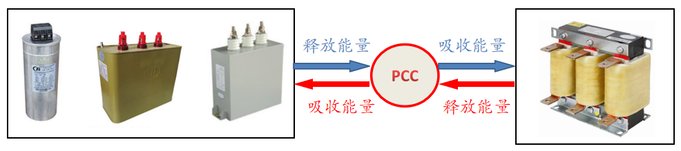
Most of the reactive loads mentioned in the system are generally inductive reactive loads. When devices with capacitive power loads are connected in parallel with inductive power loads in the same circuit, the capacitive load releases energy when the inductive reactive load absorbs energy, and vice versa. Energy is exchanged between the capacitive and inductive loads. The reactive power absorbed by the capacitive load can be compensated by the reactive power output from the capacitive load device, and the reactive power is locally balanced to reduce line losses, improve load-carrying capacity, reduce voltage losses, and alleviate the power supply pressure of the power plant. This is the basic principle of reactive compensation.
● Analyzed from the Phase (Inductive/Capacitive) Perspective
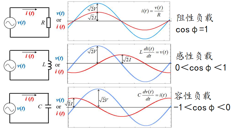
In a pure inductive load, the current IL lags the voltage by 90°, and its power is referred to as inductive reactive power. Conversely, in a pure capacitive load, the current Ic is ahead of the voltage by 9 0°, and its power is known as capacitive reactive power.
The phase difference between the current in a capacitor and the current in an inductor is 180°, which can cancel each other out. Most loads in a power system are inductive, so the total current I will lag the voltage by an angle Φ1. If a parallel capacitor is connected in parallel with the load, then I′=I+IC. The current of the capacitor will offset a portion of the inductive current, resulting in a reduction of the total current from I to I′, and the phase angle is reduced from Φ1 to Φ2. This can improve the power factor and manage reactive power locally.
04 What are the forms of reactive power compensation?
Broadly speaking, there are many forms of reactive power compensation, including:
Based on the voltage level of the point of common coupling (PCC) where compensation is applied, it can be divided into high-voltage compensation, medium-voltage compensation, and low-voltage compensation.
Based on the position of the compensation point in the power transmission and distribution system, it can be divided into on-site compensation at the equipment side, local partial compensation in the area, and centralized compensation in the substation.
Based on the type of compensation equipment, it can be divided into switching capacitor compensation (FC compensation), mechanical rotating compensation (such as synchronous compensators, synchronous generators, and synchronous motors), static reactive power compensation (static var compensators: thyristor-switched capacitors TSC, thyristor-controlled reactors TCR, magnetically controlled reactors MCR; static synchronous compensators STATCOM; static var generators SVG), and composite reactive power compensation (FC+TCR, FC+MCR, FC+STATCOM).
● Compensation forms based on compensation location
Next, we will briefly introduce the forms of reactive power compensation for low-voltage 0.4KV systems based on different compensation locations.
On-site equipment-side compensationOn-site equipment-side compensation is a method of providing reactive power补偿 to individual electrical equipment. This involves directly connecting capacitors to the same electrical circuit as the individual equipment and using the same switch for control, either simultaneously operating or disconnecting them. This compensation method has the best effect as the capacitors are close to the electrical equipment to balance the reactive current locally, avoiding overcompensation during no-load conditions and ensuring power quality. This compensation method is commonly used for high and low voltage motors and other electrical equipment. However, when the user equipment operates non-continuously, the utilization rate of capacitors is low, and their compensation benefits cannot be fully realized.
Local partial compensation in the areaLocal partial compensation in the area involves installing capacitors in groups in workshop distribution rooms or substation branch lines. These capacitors can be added or removed based on system load changes. The compensation effect is also good, but the cost is relatively high.
Centralized compensation in the substationCentralized compensation in the substation involves installing all capacitor groups on the primary or secondary busbars in the substation. This compensation method is simple to install, reliable in operation, and can collectively compensate for the reactive power of the low-voltage 0.4KV system. It has a direct effect on improving the power factor at the transformer primary side (usually a 10KV measurement point). This type of compensation method is currently the most widely used and relatively cost-effective solution.
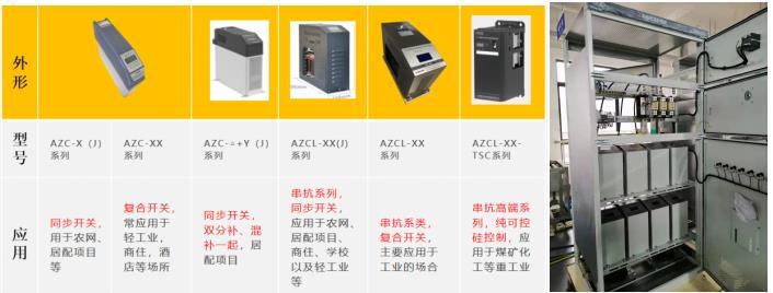
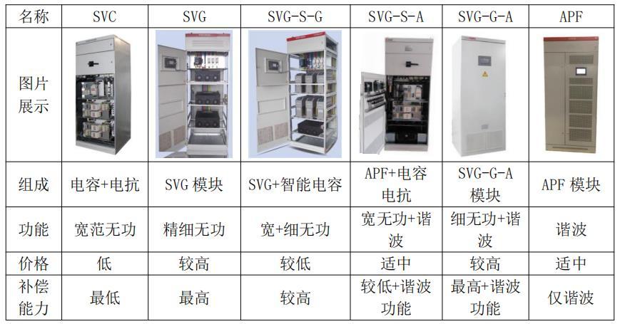
● Compensation forms based on compensation equipment types
There are many types of compensation equipment, and the choice is generally based on the actual operating equipment at the site. Each compensation device has its own advantages and disadvantages. In this article, we will briefly introduce two products that are most widely used in the 0.4KV distribution system on the market: switching capacitor compensation (FC compensation) and static var generator (SVG compensation).
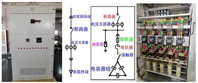
Switching Capacitor Compensation (FC Compensation)
Switching capacitor compensation is the traditional method of parallel capacitor compensation. Its principle is to increase the inductive reactive demand of the capacitive reactive compensation load to enhance the stability of the load voltage and improve the power factor.
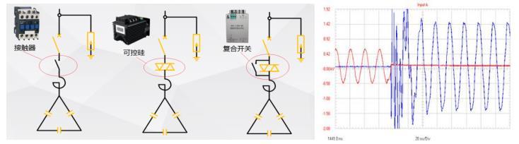
Due to the fact that the switching of parallel capacitors in earlier times was achieved through contactors, which have a response time on the second-level scale, its fatal drawback was the large inrush current during switching. In severe cases, it could reach 50-100 times the rated current of the compensation capacitor, resulting in significant arc light and causing damage to capacitors and contactors. Based on the actual operation of on-site loads, alternatives to contactors such as synchronous switches, hybrid switches, and thyristor switches have gradually emerged in the market. These alternatives have greatly improved at switching at zero voltage and interrupting at zero current, significantly reducing equipment damage caused by switching inrush current.
To achieve intelligent switching control, diversified data acquisition system, diverse protection functions, and simplified installation and maintenance, another type of switching capacitor compensation has been developed in recent years - the intelligent capacitor. Compared to traditional capacitance compensation, it has multiple technological functions that traditional capacitors cannot achieve. Additionally, with the electronification of load equipment, the impact of harmonics on the distribution system cannot be ignored, especially on capacitors. Therefore, in response to harmonic effects, FC compensation has also undergone many related improvements. For example, the concept of series reactance rate has been introduced. When should a 6% or 7% series reactance rate be used? And when should a 13% or 14% series reactance rate be used? This part will be further explained in a later topic.
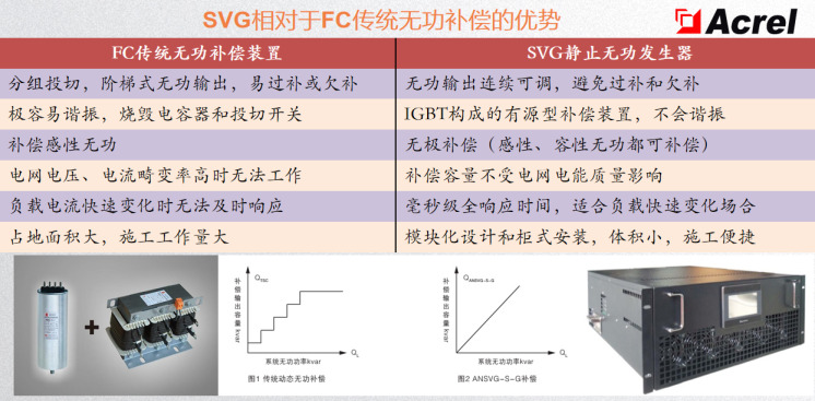
Static Var Generator (SVG) Compensation
A static var generator is a new power electronic device used for reactive power compensation. It can quickly and continuously compensate for varying amounts of reactive power and negative sequences. Its application can overcome the slow response speed, inaccurate compensation control, and the tendency to cause parallel resonance and switching oscillation in traditional reactive power compensators such as FC compensators.
Compared to FC compensation, its three major advantages are:
① Linear compensation of reactive power with a compensation step smaller than 1KVar;② Polarity-free compensation, which can output both capacitive and inductive reactive power;③ Fast response time, with a total response time less than 5ms.
Economics of Reactive Power Compensation by Tsai Ing-wen
● Compensate for reactive power to improve power factor.
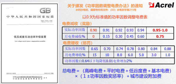
According to the notice on the "Method of Adjusting Electricity Fees Based on Power Factor", it is not difficult to find that the power factor adjustment rules take 0.9 as the standard value. By increasing the power factor, users can reduce their total electricity fees. Additionally, distribution users with a power factor higher than 0.9 may also receive rewards from the power company for power factor adjustment. Through reasonable compensation, the power factor at the measurement point can be adjusted to meet national standards, which can eliminate power factor charges and significantly reduce electricity costs for power users.
The active energy saving of dynamic reactive power compensation devices only reduces the loss in the power supply and distribution from the compensation point to the generator. Therefore, reactive power compensation on the high-voltage grid side cannot reduce the loss on the low-voltage side or improve the utilization rate of low-voltage power transformers. According to the optimal compensation theory, local dynamic reactive power compensation has the most significant energy-saving effect.
Additionally, many compensation devices in the market promote concepts such as "energy-saving" and "power saving". Most of them start with reactive power compensation, improve power factor, reduce power factor penalties, or transform power factor penalties into power factor rewards, ultimately achieving the goal of saving money for distribution users. Therefore, from the perspective of natural energy transfer in nature, reactive power compensation strictly speaking does not belong to the category of "energy-saving" or "power saving." However, it can truly save money for distribution users.
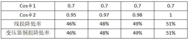
● Reducing losses in transmission lines and transformersReasonable compensation can effectively reduce system current. Taking a system natural power of 0.7 as an example, if the power factor of the system is increased to close to 1 through compensation devices, the system current will drop by about 30%. That means the loss in lines and transformers can be reduced to P=I2R=(1-30%)2R=0.49R, which is a 51% reduction in line and transformer losses. The natural power factor of an electricity enterprise is generally around 0.7. The rate of reduction in line loss and copper loss in transformers from increasing the power factor from 0.7 to above 0.95 is shown in the table below.
Reducing line and transformer losses and saving active power are important energy-saving measures. In the petroleum industry, where lines are long and complex, increasing reactive power compensation equipment can reduce operating current, thus reducing line losses and saving active power, with noticeable energy-saving effects.
● Increasing the transmission capacity of the power grid and improving equipment utilization
Compensation devices can effectively reduce system current and apparent power, thus effectively reducing the capacity of all related equipment in power grid construction and lowering investment in power grid construction. For a system with a power factor of around 0.7, effective compensation can reduce system current by 30%, which means increasing the load-carrying capacity of power plants and power transformation and distribution facilities by 30%.
If there is insufficient capacity in transformers and lines, the method of installing reactive power compensation devices can be used. Installing reactive power compensation devices can balance reactive power locally, reducing the current flowing through lines and transformers, slowing down the aging speed of wire and transformer insulation, and extending their service life. At the same time, it can release the capacity of transformers and lines, increasing their load-carrying ability. For example, with a 100KVA transformer currently operating at 85% load with a COSΦ of 0.7, installing reactive power compensation equipment can increase the transformer's load-carrying capacity by 30%. Users can increase their load without expanding capacity to facilitate further production expansion.
● Improving voltage quality
A large amount of inductive load in the system will cause voltage drop on the power lines, especially at the end of the power lines. Reasonable compensation can effectively alleviate line voltage drop and improve power quality.
The formula for calculating voltage loss in the line is as follows:
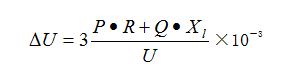
In the formula:
P - Active power, kW
U - Rated voltage, kV
R - Total resistance of the line, Ω
Q - Reactive power, kVar
Xl - Inductive reactance of the line, Ω
As the system's inductive reactance is much greater than its impedance, it can be seen from the formula that changes in reactive power can significantly affect voltage variations. When the reactive power Q in the line decreases, voltage loss also decreases.
At the end of the power supply line, the voltage is generally low. Increasing reactive compensation devices can boost the voltage at the line's end to ensure safe and reliable operation of equipment.
On the other hand, with the development of industry, the use of a large number of automatic control equipment and nonlinear loads has resulted in a significant flow of harmonics in the power distribution network, contaminating the grid. One of the main ways to improve power quality is to抑制or significantly reduce the impact of harmonics on the power supply system and electrical equipment through reasonable allocation of compensation filtering equipment.
Finally, with the rise of new power systems, power quality issues are bound to face many power quality related issues, the following issues are worth further understanding, familiarization, and exploration:
1.Analysis of resonance issues, what is resonance?
2.What are the common scenarios where filters are often damaged?
3.What is the difference between local compensation and centralized compensation of filters?
4.How to understand the requirement of reducing harmonics to 5%?
5.Can installing filters really achieve "energy saving"?
6.How does the integration of power electronic devices such as energy storage, photovoltaic, and wind power affect power quality?
7.Is the demand for power quality in microgrid systems important?
8.... (and so on)