We will present the performance, safe operation methods, and technical parameters of KYN61-40.5 medium-voltage switchgear
Model and meaning
K Y N 61 - 40.5 / □ - □
└─Rated Breaking Short Circuit Current (kA)
└───Rated current (A)
└─────── Rated Voltage (kV)
└────────── design serial number
└ ───────────── indoors
└────────────── Removal type
└─────────────── Metal armor
Use environmental conditions
The upper limit of ambient temperature is +40°C, and the average measured value within 24 hours does not exceed 35°C.
Lower limit -15°C:
Altitude: no more than 1000 meters above sea level;
Relative humidity: daily average not more than 95%, monthly average not more than 90%;
Earthquake intensity: no more than 8 degrees;
Water vapor pressure: the daily average does not exceed 2.2kPa, and the monthly average does not exceed 90%.
Technical parameters
Main technical parameters of vacuum switchgear
serial number | project | Dimensions | parameter |
1 | Rated voltage | kV | 40.5 |
2 | Lianchang | A | 12501600 2000 |
3 | Rated frequency | Hz | 50 |
4 | Rated for short-term withstand current | kA | 20 25 31.5 |
5 | Rated peak withstand current | kA | 50 63 80 |
6 | rated power frequency withstand voltage | kV | 95/1 min |
7 | Rated lightning shock withstand voltage | kV | 185 |
8 | Rated short circuit duration | S | 4 |
9 | Protection level | IP3X |
Main technical parameters of vacuum circuit breaker
serial number | project | Weaving position | parameter |
1 | Rated voltage | kV | 40.5 |
2 | Rated frequency | Hz | 50 |
3 | rated power frequency withstand voltage | kV | 95/lmin |
4 | Rated lightning shock withstand voltage | kV | 185 |
5 | Rated current | A | 12501600 2000 |
6 | Rated for short-term withstand current | kA | 20 25 31.5 |
7 | Rated short-circuit breaking current | KA | 20 25 31.5 |
8 | Rated peak withstand current | kA | 50 63 80 |
9 | Rated short circuit duration | ms | 4 |
10 | Opening time | ms | 30 S 1 W 60 |
11 | Hehe time | ms | 50 & t W 】00 |
12 | 88 The number of times the current is interrupted in a fixed short circuit | times | 20 |
13 | Mechanical life | times | 10000 |
The main technical parameters of spring operation machinery
name | unit | numeric value | |
Rated operating voltage | Split coil | V | DC220/110 AC220/110 |
Closing coils | |||
Rated operating current | Split coil | A | O.96(22OV)1.O5I11OV) |
Closing coils | |||
Energy storage motor power | W | 230 | |
Energy storage motor rated voltage | V | DC220/110 AC220/110 | |
Energy storage time | S | w 12 |
Structural characteristics of switchgear
The switchgear is designed according to the GB3906-1991 and IEC298 standards for armored metal-enclosed switchgear. The whole is composed of two parts: the cabinet and the extractable part (handcart). The cabinet structure is prefabricated and bolted together. The inner part of the switchgear is divided into a circuit breaker room, a main busbar room, a cable room and a relay instrument room with a metal partition. The protection level of the enclosure reaches IP3X, the protection level between each compartment is IP2X, and all metal structural parts are reliably grounded, and each compartment of the main circuit system has an independent exhaust pressure release channel.
1. Enclosure and partition
The shell and partition of the switchgear are bolted together with cold-rolled steel plates after being processed and bent by CNC machine tools. Therefore, the assembled switchgear can ensure the uniformity of the structural dimensions. The switchgear is divided into a circuit breaker room, a main busbar room, a cable room and a relay instrument room, and each part is separated by a grounded metal partition.
2. Handcart
Handcarts can be divided into circuit breaker handcarts, voltage transformer handcarts, metering handcarts, isolation handcarts, etc. according to the purpose
The handcart has a test/isolation position and a working position in the cabinet, and each position is equipped with a joint silver device to ensure that the handcart cannot be moved casually when it is in the above two positions.
3. Circuit breaker compartment
Specific tracks are installed inside the circuit breaker compartment for the handcart to move. When the circuit breaker moves between the working positions of the test position, the isolation flap is automatically opened or closed, which ensures that the staff does not
Touch the charged body. The handcart can be operated with the cabinet door closed, and the handcart can be seen in the cabinet through the viewing window, as well as any function signs on the handcart.
4. Busbar chamber
The main bus leads from one switchgear to another by means of a branch busbar and a static contact box, which is fixed with a busbar sleeve when crossing the side panels of the adjacent cabinet. All busbars are insulated by composite insulation.
5. Cable compartment
PT, ground switch, surge arrester and multiple cables can be installed in the cable room.
6. Relay room
The relay chamber plate and panel can be installed with secondary components such as control, protection elements, metering, display instrumentation, live monitoring indicator, etc.
7. Interlock device
The switchgear has a reliable interlock device to ensure the safety of operators and equipment:
 |  |  |
| Promote interlocking installation | KYN61-40.5(Z) Armored Handcart Cabinet | Grounding switch |
When the grounding switch is in the opening position, the handcart can be moved from the test/isolation position to the working position: and the rear door cannot be opened, which prevents mistakenly entering the live interval.
When the handcart is completely pulled out of the cabinet or when the handcart is grounded in the test/isolation position in the cabinet to open the lock and unlocker, the grounding switch can be closed; When the handcart is in the working position, the grounding switch cannot be closed. It prevents the live misconnection of the grounding switch and prevents the multi-handed cart from moving to the working position when the grounding switch is in the closed position.
The circuit breaker handcart can only operate the circuit breaker when it is in the test/isolation position or working position: and after the circuit breaker is named, the handcart cannot move, which prevents the live load from accidentally pushing and pulling the circuit breaker. Electrical interlocks can be installed between each cabinet.
Grounding device
In the cable room, there is a separate 6x50mm2 grounding busbar, which can run through the adjacent cabinets and have good contact with the cabinets.
Main wiring scheme
There are 27 commonly used typical schemes for the primary wiring scheme of the switchgear, which can meet the needs of users for cable entry and exit lines, overhead entry and exit lines, contact and measurement, protection, etc.
Scheme number | 01 | 02 | 03 | 04 | |
Main wiring diagram | 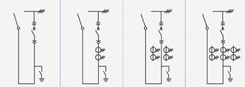 | ||||
Main electrical equipment | Rated current | 125,016,002,000 | |||
New circuit driver ZN85-40.5 | 1 | 1 | 1 | 1 | |
Current transformer LDBJ8(9)-35 | 2 | ||||
Grounding switch IN22-40.5/31.5 | 1 | 1 | 1 | 1 | |
use | Overhead out | Overhead out | Overhead out | Overhead out | |
Scheme number | 05 | 06 | 07 | 08 | |
Main wiring diagram |  | ||||
Main electrical equipment | Rated current | 125,016,002,000 | |||
New circuit driver ZN85-40.5 | 1 | 1 | 1 | 1 | |
Current transformer LDBJ8(9)-35 | 2 | 3 | |||
Grounding switch IN22-40.5/31.5 | 1 | 1 | 1 | 1 | |
use | cable outlet | cable outlet | cable outlet | cable outlet | |
Scheme number | 09 | 10 | 11 | 12 | |
Main wiring diagram |  | ||||
Main electrical equipment | Rated current | 125,016,002,000 | |||
New circuit driver ZN85-40.5 | 1 | 1 | 1 | 1 | |
Current transformer LDBJ8(9)-35 | 1 | 2 | 3 | ||
use | Left (right) contact | Left (right) contact | Left (right) contact | Left (right) contact | |
Scheme number | 13 | 14 | 15 | 16 | |
Main wiring diagram | 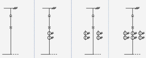 | ||||
Main electrical equipment | Rated current | 125,016,002,000 | |||
New circuit driver ZN85-40.5 | |||||
Current transformer LDBJ8(9)-35 | 1 | 2 | 3 | ||
use | contact | contact | contact | contact | |
Scheme number | 17 | 18 | 19 | 20 | |
Main wiring diagram |  | ||||
Main electrical equipment | Rated current | 125,016,002,000 | |||
New circuit driver ZN85-40.5 | 1 | 1 | 1 | 1 | |
Current transformer LDBJ8(9)-35 | 1 | 2 | 3 | ||
use | Cable in | Cable in | Cable in | Cable in | |
Scheme number | 21 | 22 | 23 | 24 | |
Main wiring diagram |  | ||||
Main electrical equipment | Rated current | 125,016,002,000 | |||
New circuit driver ZN85-40.5 | 1 | 1 | 1 | 1 | |
Current transformer LDBJ8(9)-35 | 1 | 2 | 3 | ||
use | Overhead in | Overhead in | Overhead in | Overhead in | |
Scheme number | 25 | 26 | 27 | 28 | |
Main wiring diagram |  | ||||
Main electrical equipment | Rated current | 125,016,002,000 | |||
Voltage transformer LDX9-35 | |||||
Fuse XPNP-35 | 2 | 3 | 2 | ||
Surge arrester YH5WS-51/134Q | 3 | ||||
| Transformer SCB9-50-35/0.4 | 1 | ||||
use | Voltage transformer | Voltage transformer | Station usage changed | ||
Dimensions and schematic diagram of switchgear structure
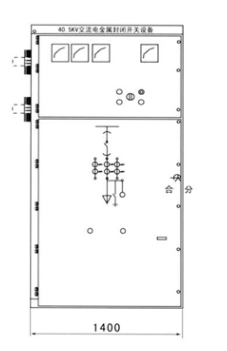 | 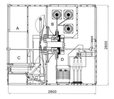 |
| Dimensions (WxDxH): 1400x2800x2600 | Schematic diagram of the structure of the switchgear A relay instrument room B bus room C circuit breaker room D cable |
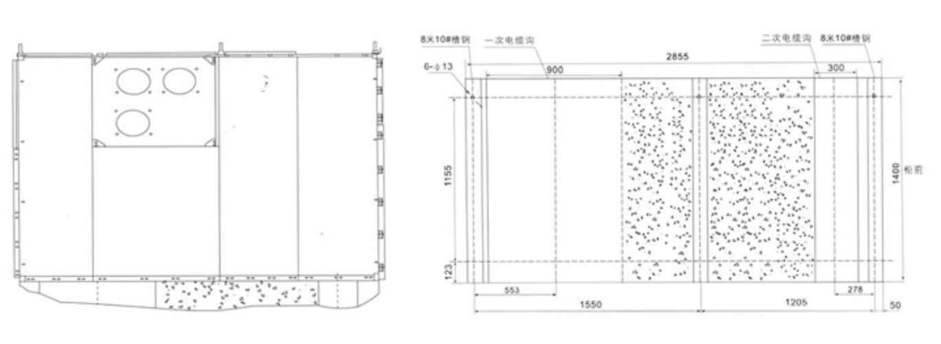
Switch cabinet installation
1. Height of electrical room: ≥4500mm:
2. Distance from the back of the cabinet to the wall: ≥1500mm;
3. Flatness of foundation frame: ≤1mm/m?;
4. The part of the foundation embedded channel steel above the ground shall not exceed 3mm;
5. It can be fixed on the foundation by bolting or welding:
6. The weight of the switchgear is about 1800Kg:
7. Width of the switchgear operation corridor (single row): ≥3000mm, double row (face to face) ≥ 4000mm.
Product consistency
the main scheme number of the secondary line, the single bus system diagram, the arrangement diagram and the layout diagram;
Secondary circuit electrical schematic diagram and terminal arrangement diagram:
the model, specification and quantity of electrical components of the switchgear;
Specifications and materials of main busbars and branch busbars:
Name and quantity of spare parts and spare parts:
Special requirements are agreed with the manufacturer.
Due to the continuous improvement of product technology, all data should be confirmed by the latest technical department of the factory, and there will be changes without prior notice.
Ordering instructions
The user should provide the following technical information when ordering:
Main wiring scheme diagram, purpose and single-wire system diagram: rated voltage: rated current: rated short circuit breaking current: distribution room layout diagram and switchgear arrangement and configuration diagram, etc.
Indicate the specifications of the inlet and outlet cables.
Requirements for control, measurement and protection functions of switchgear and other requirements for latching and automatic devices.
The model, specification and quantity of the main electrical components in the switchgear. Such as switchgear between! or the incoming cabinet needs to be connected by a busbar bridge, and specific requirements such as the rated ampacity of the busbar bridge and the span of the busbar bridge from the ground height should be provided.
When switchgear is used in special environments, it should be detailed at the time of ordering.
Other special requirements.
Schematic diagram of the installation of switchgear