We will present the performance, safe operation methods, and technical parameters of XGN2-12 medium-voltage switchgear
Scope of application
XGN port-12 box type fixed metal enclosed switchgear (referred to as ring network cabinet) is suitable for AC 50Hz, 10KV network as a break load and short circuit and closing short-circuit current, this ring network cabinet is equipped with manual and electric spring mechanism to operate the load switch, and the ground switch and isolation switch are equipped with manual operation mechanism. This ring network cabinet has strong complete performance, small size, no fire and explosion hazard, and has a reliable "five prevention" function.
Use environmental conditions
The upper limit of ambient temperature is +40°C, and the lower limit is -25°°C;
The altitude does not exceed 1000m;
the daily average of air relative humidity is not greater than 95%, and the monthly average is not greater than 90%; The daily average of water vapor is not greater than 2.2x10⁻³Mpa, and the monthly average is not greater than 1.8×10⁻³Mpa;
The surrounding air is not corroded or obviously polluted by combustible gases and water vapors;
No regular violent vibrations.
Model and meaning
XGN□-□-□-□/□-□
└──Rated Thermal Stable Current (kA)
└──Rated current (A)
└──Operation method (J spring operation D electromagnetic operation.)
└── One plan number
└──Rated voltage
└──Design serial number
└──Indoors
└──Fixed
└──Box type
Use environmental conditions
◆Upper limit of ambient temperature +40°C lower limit -25°C (indoor):
◆Allocation 1000m;
(When the water altitude exceeds 1000m, it shall be implemented in accordance with the relevant provisions of DUT593-1996 "Technical Guidelines for Shared Ordering of High-voltage Switchgear");
◆The daily average of relative humidity is not greater than 95%, and the monthly average is not greater than 90%:
the intensity of ground tremors does not exceed 8 degrees;
◆ No fire, explosion hazard, serious pollution, chemical corrosion and violent perturbation place.
The main technical parameters of the switchgear
serial number | project | unit | data |
1 | Rated voltage | kV | 3、6、10 |
2 | Maximum operating voltage | kV | 3.5、8.9、11.5 |
3 | Rated current | A | May-00 |
4 | Rated breaking current | kA | 16.20、31.5、40 |
5 | Rated Short Circuit Engagement (Rated Short Circuit Off Current) | kA | 40、50、80.100 |
6 | Rated short-circuit thermal stabilization current | kA | 16.20、31.5、40 |
7 | Rated for thermally stable current | kA | 40、50、80、100 |
8 | Rated thermal settling time | s | 4 |
9 | Protection level | IP | IP2X |
10 | Busbar system | - | Single busbar, next to the single busbar |
11 | How it works | - | Electromagnetic type, spring energy storage type |
12 | Dimensions (width, × depth, × height). | mm | 1100×1200×2650 (below 1000A). |
13 | weight | kg | 1000 |
Structure and anti-error device
structure
The cabinet is a metal enclosed armored structure, the cabinet skeleton is welded by angle steel, and the cabinet is divided into a circuit breaker room, a busbar room, a cable room, and a relay room, and the operation of the main components in the cabinet can be observed through the observation window and lighting on the façade. In order to improve the technical performance of the switchgear, the main components (such as circuit breakers, rotary disconnect switches, etc.) have been redesigned.
According to the layout of the cabinet, the relay room is installed with a relay, the door can be equipped with signal relay, indicator instrument, signal light, transfer switch installation and operation chamber, the rear is the busbar room, the lower part is the cable room, the user can easily wire. The front is the circuit breaker room, which facilitates the maintenance of the switchgear. The internal mechanism of the cabinet is shown in Figure 1, Figure 2 and the product manual.
Error prevention device
The "five prevention" functions are: to prevent misdisconnection and misconnection of circuit breakers; Prevent misidentification and misclosing of the disconnect switch with load; prevent live shutdown and ground switch; prevent the power supply from being turned on when the ground is opened and closed; Prevents misentry into live intervals.
This switchgear adopts the compulsory mechanical locking method, and the anti-error device is composed of main components such as supports, discs, panels, locking plates, handles, and connecting rods, which have the characteristics of reliable performance, complete functions, simple structure and easy operation, so as to achieve the "five preventions" simply and effectively:
(1) Control switches (KW switches) with red and green plates are used in circuit breaker schemes to prevent misdisconnection and misclosing of circuit breakers;
(2) Only after the circuit breaker is indeed disconnected, the small handle can be pulled out of the "working" position and dialed to the right to the "disconnection locking" position; Split and close isolation switches; Prevent load division and closing isolation switches. The reliability of latching and anti-locking has dual error prevention functions, that is, when the small handle is in the "disconnection and locking" position, it can only close and divide the upper and lower isolation switches, and cannot close the circuit breaker, avoiding the misclosing of the circuit breaker;
(3) When the circuit breaker and the upper and lower isolation switches are in the closed state and the small handle is in the "working" position, the front and rear cabinet doors cannot be opened to prevent mistakenly entering the live interval;
(4) When the upper and lower isolation switches are opened, the grounding switch cannot be closed, and the small handle cannot be dialed from the "break-lock" position to the "maintenance" position, which can prevent the live from hanging the grounding wire;
(5) If the grounding switch is not opened, the upper and lower isolation switches cannot be closed, which can prevent the disconnect switches with the grounding wire from closing.
XGN□ - 12/07D outline (Fig. 1)
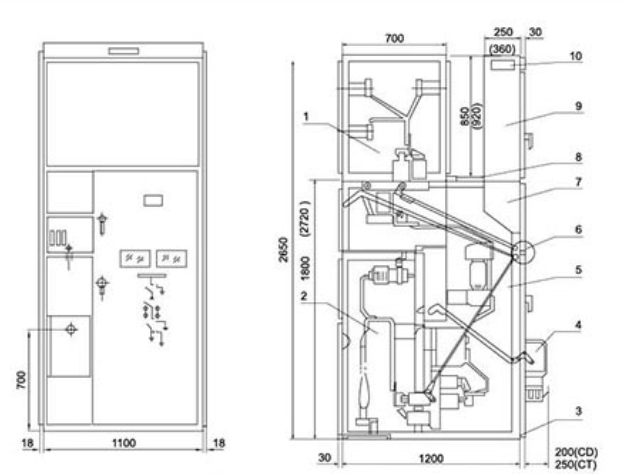
1. Busbar room 2. Cable room 3. Grounding bus 4. Electromagnetic (spring) mechanism 5. New circuit device room
6. Manual operation and joint sales mechanism 7. Operation chamber 8. Pressure release channel 9. Instrument room 10. Small bus terminal
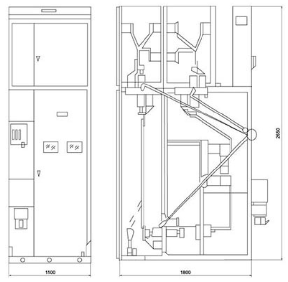
XGN-12 (bypass cable outlet) outline (Fig. 2)
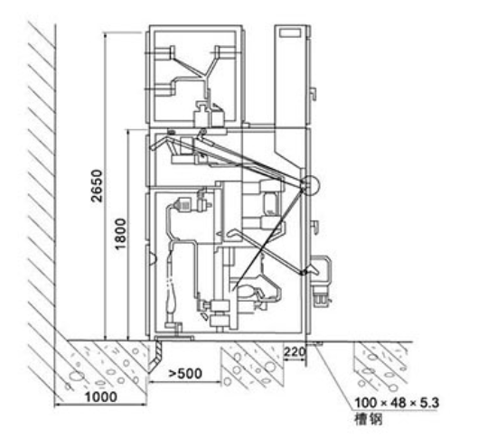
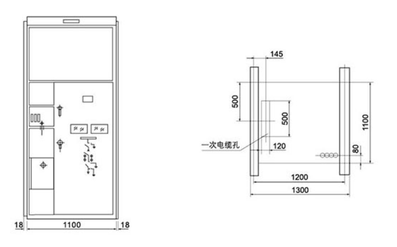
Dimensions installation drawing