We will present the performance, safe operation methods, and technical parameters of KYN28-12 medium-voltage switchgear
Use environmental conditions
◆Ambient air temperature: Upper limit +40°C Lower limit -10°C in general areas:
◆Altitude: 1000m;
◆Humidity:
Relative humidity: the daily average is not greater than 95%, and the monthly average is not greater than 90%;
Water vapor pressure: the daily average is not greater than 2.2KPa, and the monthly average is not greater than 1.8KPa
Condensation may occur when the temperature plummets, accompanied by dirt, and this product is suitable for two environmental conditions that are harsher than the following normal conditions:
(1). Infrequent condensation (no more than twice a month on average) with mild dirt;
(2). Generally no condensation (no more than twice a year on average) with serious pollution;
◆ There are no fire, explosion hazards and serious pollution enough to corrode metal and damage insulation and other harsh places;
◆There are no violent vibrations, bumps and vertical inclination of no more than 80;
Note: (1) Storage and transportation are allowed at -30°C;
(2) When the altitude exceeds 1000m, it shall be handled in accordance with JB/2102 "Technical Requirements for Altitude Areas for the Use of High-Voltage Electrical Appliances"; When the altitude does not exceed 2000m, the low-pressure auxiliary equipment does not need to take any measures;
(3) When the actual conditions of use are different from the above, it should be negotiated between the user and the manufacturer.
Model and meaning
K Y N 28 - 12/ □ - □
└─Rated Breaking Short Circuit Current (KA)
└─Rated Current (A)
└─Rated voltage (KV).
└─Design serial number
└─Indoors
└─ Move the type
└─Metal armor
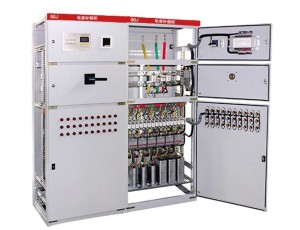
Schematic diagram of the structure of the switchgear
Figure 1

A. Circuit breaker compartment B. Busbar compartment
C. Cable room D. Relay instrument room
1. Busbar 2. Static contact disc 3. Circuit breaker
4. Grounding switch 5. Current transformer
6. Capacitive voltage divider 7. Lightning arrester
Fig.2 Schematic diagram of switchgear structure

1. Housing 2. Branch small busbar 3. Busbar sleeve 4. Main busbar
5. Static contact device 6. Static contact box 7. Current transformer
8. Grounding switch 9. Cable 10. Surge arrester 11. Grounding main bus
12. Loading and detachable partition 13. Partition (flap) 14. Secondary plug
15. Circuit breaker handcart 16. Heater device 17. Extractable horizontal partition
18. Grounding switch operating mechanism 19. Base plate
A.Busbar room B. Circuit breaker handcart room C. Cable room D. Relay instrument room
1.1. Pressure relief device 1.2. Control small trunking
Meet the standards
The product meets the following standards:
1.IEC-298
2.GB3906-1991
3.DLT404-19974. GB/T11022-1999
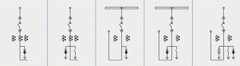
Primary wiring scheme
| Scheme number | 001 | 002 | 003 | 004 | 005 | |
Primary route diagram |
| |||||
| Rated current (A). | 630-4000 | |||||
One times host want electricity utensil Yuan item | Vacuum circuit breaker | 1 | 1 | 1 | 1 | 1 |
| Current transformer LZZBJ9-12 | 2 | 2 | 2 | 3 | 3 | |
| Voltage transformer RZL/REL | ||||||
| High Pressure Breaker (XRNP □) | ||||||
| Grounding Switch (EK6/JN15-12) | 1 | 1 | 1 | |||
| Surge arrester HY5WZ-17/45 | 3 | |||||
| use | Receiving power and feeding power | Receiving power and feeding power | Receiving power and feeding power | Receiving power and feeding power | Receiving power and feeding power | |
| Scheme number | 006 | 007 | 008 | 009 | 010 | |
Primary route diagram |
| |||||
| Rated current (A). | 630-4000 | |||||
One times host want electricity utensil Yuan item | Vacuum circuit breaker | 1 | 1 | 1 | 1 | 1 |
| Current transformer LZZBJ9-12 | 3 | 2 | 2 | 2 | 2 | |
| Voltage transformer RZL/REL | ||||||
| High Pressure Breaker (XRNP □) | ||||||
| Grounding Switch (EK6/JN15-12) | 1 | 1 | 1 | |||
| Surge arrester HY5WZ-17/45 | 3 | |||||
| use | Feed | Contact (right) | Contact (right) | Contact (left) | Contact (left) | |
| Scheme number | 011 | 012 | 013 | 014 | 015 | |
Primary route diagram |
| |||||
| Rated current (A). | 630-4000 | |||||
One times host want electricity utensil Yuan item | Vacuum circuit breaker | 1 | 1 | 1 | 1 | 1 |
| Current transformer LZZBJ9-12 | 3 | 3 | 2 | 2 | 2 | |
| Voltage transformer RZL/REL | ||||||
| High Pressure Breaker (XRNP □) | ||||||
| Grounding Switch (EK6/JN15-12) | 1 | 1 | 1 | |||
| Surge arrester HY5WZ-17/45 | 3 | |||||
| use | Overhead Line (Right Contact) | Overhead Line (Right Contact) | Overhead entry and exit lines | Overhead entry and exit lines | Overhead entry and exit lines | |
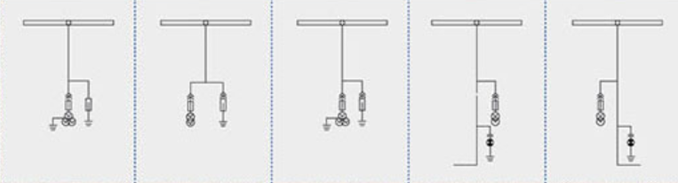
| Scheme number | 016 | 017 | 018 | 019 | 020 | |
Primary route diagram |
| |||||
| Rated current (A). | 630-4000 | |||||
One times host want electricity utensil Yuan item | Vacuum circuit breaker | |||||
| Current transformer LZZBJ9-12 | ||||||
| Voltage transformer RZL/REL | /3 | 2/ | /3 | 2/ | /2 | |
| High Pressure Breaker (XRNP □) | 3 | 3 | 3 | 3 | 3 | |
| Grounding Switch (EK6/JN15-12) | ||||||
| Surge arrester HY5WZ-17/45 | 3 | 3 | 3 | |||
| use | Voltage measurement + surge arrester | Voltage measurement + surge arrester | Voltage measurement + surge arrester | Voltage Measurement (Left link) | Voltage Measurement (Right Link) | |
| Scheme number | 021 | 022 | 023 | 024 | 025 | |
Primary route diagram |
| |||||
| Rated current (A). | 630-4000 | |||||
One times host want electricity utensil Yuan item | Vacuum circuit breaker | |||||
| Current transformer LZZBJ9-12 | 2 | 2 | 3 | 3 | 2 | |
| Voltage transformer RZL/REL | 2/ | 2/ | 2/ | 2/ | /3 | |
| High Pressure Breaker (XRNP □) | 3 | 3 | 3 | 3 | 3 | |
| Grounding Switch (EK6/JN15-12) | ||||||
| Surge arrester HY5WZ-17/45 | ||||||
| use | Measurement + right couplet | Measurement + left couplet | Measurement + left couplet | Measurement + right couplet | Measurement + left couplet | |
| Scheme number | 026 | 027 | 028 | 029 | 030 | |
Primary route diagram |
| |||||
| Rated current (A). | 630-4000 | |||||
One times host want electricity utensil Yuan item | Vacuum circuit breaker | 1 | ||||
| Current transformer LZZBJ9-12 | 3 | Capacitor Bm12.7-16-1 3 | ||||
| Voltage transformer RZL/REL | /3 | Transformer 1 | /4 | /4 | ||
| High Pressure Breaker (XRNP □) | 3 | 3 | (XRNT)3 | 3 | 3 | |
| Grounding Switch (EK6/JN15-12) | 1 | 1 | 1 | |||
| Surge arrester HY5WZ-17/45 | 3 | 3 | 3 | |||
| use | Incoming + metering | Transformer cabinet used (cabinet width is determined according to the size of the variable size used) | Capacitor cabinets | Voltage measurement + surge arrester | Voltage measurement + surge arrester | |

◆A handcart The handcart skeleton is made of thin steel plates processed by CNC machine tools and then riveted and welded. According to the application, the handcart can be divided into circuit breaker handcart, voltage transformer handcart, isolation handcart, metering handcart and other handcarts of the same specification, which are convenient for interchangeability. The handcart has an isolation position, a test position and a working position in the cabinet, and each position is equipped with a positioning device to ensure that the handcart cannot be moved casually when it is in the above position, and the interlock must be released when the handcart is moved. |
|
◆B busbar The bus leads from one switch cabinet to another by means of a branch bus and a static contact tray. The flat branch bus is bolted to the static contact tray and the main bus, without the need for any additional clamps or breakout connections. When the user and the project have special needs, the connecting bolts on the busbar can be encapsulated with insulation and end caps. When the busbar crosses the switchgear partition, it is fixed with a busbar sleeve. If there is an internal fault arc, it can limit the spread of the accident to the adjacent cabinet and ensure the mechanical strength of the busbar. |
|
◆C cable room Current transformers, grounding switches, lightning arresters and cables can be installed in the cable room, and removable aluminum plates with slits are prepared at the bottom of the cable room to ensure the convenience of on-site construction. |
|
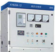
◆D Relay instrument room The relay instrument room is used to install various relays, instruments, signal indications, operation switches and other components. In addition, a small busbar room can be added to the top of the instrument room according to user requirements, and a sixteen-way control bus can be laid. |
|
◆Lock structure The connection between the middle door and the cabinet adopts a lock structure, and is equipped with a lifting mechanism to make the middle door more convenient to open, and when the middle door is closed, the connection strength between it and the cabinet is better, which enhances the ability to effectively resist the internal arc combustion fault. |
|
◆D Relay instrument room The instrument room door is closed, and the instrument room is in front view. | ◆Pressure relief device When the circuit breaker or the main busbar, cable room has an internal fault arc, with the appearance of electricity, the air pressure inside the switchgear rises, and after reaching a certain pressure, the pressure release metal plate of the top device will be automatically opened to release pressure and discharge gas to ensure the safety of the operator and the switchgear. |