We will present the performance, safe operation methods, and technical parameters of transformer:S9\S11\S13 Liquid Filled Transformers

This manual is applicable to fully sealed oil-immersed power transformers produced by our company, with a rated capacity of 3150KVA and below, and a voltage level of 35KV and below.
1. Uses and characteristics
In addition to being suitable for general power transformers, fully sealed oil-immersed transformers are especially suitable for petrochemical, metallurgy, textile, light industry, and enterprises, mines, and rural areas with high humidity and inconvenient maintenance.
This product cancels the oil protection device such as oil storage cabinet and moisture absorber to ensure that the transformer oil does not come into contact with the air, all seals are sealed with excellent special rubber, using vacuum oil injection, under normal circumstances, the transformer can be used continuously for 20 years without any treatment, low maintenance cost is the main feature of this product, and the operation reliability is enhanced, the service life is extended.
2. Model description
S□-M-□ □
S - three phases
□ - Performance Level Code (11, 13, 20)
M – sealed
□ – Rated capacity (kVA)
□ – High Voltage Voltage Level (10kV)
3. Transportation
1. During transportation and installation, when lifting the transformer, the four cranes on the fuel tank should be used at the same time to bear the total weight of the transformer after the final assembly of the transformer is filled with the amount of transformer oil. If this requirement cannot be met, a special beam lifting transformer should be used.
2. The fastening parts of this product are all loosening nuts to ensure reliable fastening. However, during transportation, it is still necessary to ensure that the transformer has sufficient stability, and the slope of the transformer should not be greater than 15°. When lifting, it should be lifted and released gently, and under the condition of no lifting equipment, the ground should move slowly to prevent violent vibration.
4. Acceptance and storage
1. After receiving the transformer, the user should immediately check the product model and specifications received according to the nameplate, whether the specifications are consistent with the order contract, and then carefully check whether there is damage to each part of the transformer, whether the vulnerable parts, such as signal thermometers, casings, etc. are damaged, and whether the signal thermometer hose is flattened and broken. Special attention should be paid to the integrity of the porcelain sleeve, which is judged according to whether there is oil seepage in the casing, and check whether there is oil leakage or oil leakage in each sealing part of the transformer.
2. If the transformer is not installed and put into operation immediately and needs to be stored for a long time, all seals should be sealed, spare parts should be properly stored, and the storage situation should be checked regularly.
5. Installation and maintenance of transformers
1. Installation of transformers
1.1 The user uses a forklift or other handling tools to smoothly transport the transformer to the designated installation position.
1.2 Be careful not to damage the casing and other wearing parts during installation, and do not scratch the fuel tank or scratch the paint film.
2. Inspection and judgment criteria before the transformer is put into operation
2.1 After the fully sealed oil-immersed power transformer is transported to the user, there is no need to check the core.
2.2 The transformer should be tested according to the "Test Standard for the Handover of Electrical Equipment in Electrical Installation Engineering".
2.2.1 Measure the DC resistance of the winding and the sleeve, and the value should not be greater than 2% compared with the factory measured value at the same temperature.
2.2.2 Check the changes of all taps and there should be no significant difference compared with the factory data.
2.2.3 Check whether the coupling group designation of the transformer is consistent with the nameplate mark.
2.2.4 The insulation resistance value should be close to the factory value at the same temperature, and should not be less than the value in Table 1.
Table 1 Insulation resistance value (MΩ)
temperature
| 20 | 30 | 40 | 50 | 60 |
<6 | 400 | 200 | 100 | 50 | 25 |
6 or more but less than 20 | 800 | 400 | 200 | 100 | 50 |
20 or more than 60 | 1000 | 500 | 250 | 125 | 65 |
Description: 1. The coil under test is grounded during the measurement. 2. Use a 2500V megaohm meter or a special meter.
2.2.5 The external construction frequency withstand voltage test voltage of the winding and the casing is shown in Table 2.
Table 2 Experimental standards for insulation power frequency withstand voltage of high-voltage electrical equipment
Rated voltage (KV). | 3 | 6 | 10 | 15 | 20 | 35 |
Factory experimental value | 18 | 25 | 35 | 45 | 55 | 85 |
Handover experimental values | 15 | 21 | 30 | 38 | 47 | 72 |
2.2.6 The conventional test items of transformer oil are inspected according to the requirements of new oil (before putting into operation), see Table 3.
Table 3 Experimental items and standards of transformer oil before putting into operation
serial number | Items | New oil in the tank before putting into operation |
1 | appearance | Transparent and free of impurities |
2 | Flash point C (sealed) | 140 |
3 | Moisture mg/1 (ppm). | ≤20 |
4 | Acid value mgKOH/g | <0.03 |
5 | Breakdown voltage KV (2.5mm) oil gap | 35KV and below: ≥35 |
6 | The medium is lost tangentially tangents by 8% (90°C). | ≤0.7 |
7 | Interfacial tension mN/m (25°C). | ≥35 |
8 | Water-soluble acid (PH). | ≥5.4 |
2.2.7 Oil sample collection method
(1) Scrub and dry the glass test cup with a diameter of about 80-100mm and the syringe barrel of about 100ml.
(2) Unscrew the oil sample valve cover at the bottom of the fuel tank.
(3) Wipe the oil sample valve outlet and vicinity clean with clean paper or cloth.
(4) Align the glass test cup with the valve outlet.
(5) Use a wrench to slowly unscrew the bolt of the oil sample valve to let the oil flow into the cup, and at the same time put the syringe needle into the oil outlet of the oil sample valve to draw the oil sample.
(6) The amount of oil sample is determined by the user according to the needs of the experimental project.
(7) When the oil sample is collected, tighten the oil sample valve bolt and valve cover.
(8) Open the oil injection pipe cover on the upper part of the transformer box cover, and slowly pour the transformer oil of the same model, the same weight, and passed the test into the oil injection pipe, and tighten the oil injection pipe cover, and the oil sample and oil replenishment process are completed.
3. Maintenance of transformers
3.1 The maintenance and inspection standards of fully sealed oil-immersed transformers are as follows in Table 4 and Table 5.
Table 4 Regular inspection standards
serial number | Inspection items | Inspection essentials | Cycle | Judgment criteria | remark |
1 | Insulation resistance | Use a 2500V rocking meter or a measuring instrument with the same effect Measure the phase to the ground | Irregular | 35KV side: 270MΩ 10KV side: 200M Ω 1KV side: 50MΩ | After a serious overvoltage or serious accident, this experiment is carried out |
2 | Insulating oil | Chromatographic analysis | 6 years | GB7252-87 "Guidelines for the Analysis and Judgment of Dissolved Gas in Transformer Oil" | After a serious overvoltage or serious accident, this experiment is not limited by the period |
3 | thermometer | 1. Internal spot inspection (rust and moisture absorption) 2. Gask condition 3. Temperature indication, indicating action 4. Temperature rating | 2 years | 1. No rust 2. No damage 3. Indicate normal action (gently tap) 4.85°C | |
4 | Oil level gauge | 1. External inspection 2. Whether the oil surface is full of oil | 1 year | 1. No rust, no oil stains on the glass 2. Whether the oil surface line can be seen | There is no oil level gauge This item will not be inspected |
5 | casing | 1. Terminal status 2. Sleeve status 3. Does oil leak? | 2 years | 1. There is no loosening or discoloration 2. There is no damage or defacement 3. No oil leakage or air leakage | If there is any abnormality, it should be dealt with in time |
6 | Grounding wire | Rugged state | 2 years | No loosening, no broken wires | |
7 | pressure release valve | 1. Whether the seal is oily 2. Whether the lead wire connection is firm | 2 years | 1. No oil seepage 2. If there is any abnormality, it should be dealt with in time | If there is leakage Deal with it in a timely manner |
Table 5 Daily inspection standards
serial number | Inspection items | Inspection essentials | Cycle | Judgment criteria | remark |
1 | Body appearance | There is no dirt, cracks or oil seepage | January | There should be no dirt, cracks, oil leakage, etc | If there is any abnormality, it should be dealt with in time |
2 | The sound and odor of the body | Abnormal sounds and smells (hearing, smell) | January | 1. Sounds and vibrations caused by excitation are normal 2. Abnormal sounds such as loosening and discharging of the fastening nut of the conductive part 3. The combustion of insulation will have a special odor | If there is any abnormality, investigate the cause and deal with it in a timely manner |
3 | Body temperature | Whether the temperature rise is normal | January | The load current borne by the transformer is related to the temperature rise of the oil surface | If there is any abnormality, investigate the cause and deal with it in a timely manner |
4 | Body oil surface | Whether the oil surface is normal (oil surface table) | January | The oil should be filled with an oil level gauge | If there is no oil level gauge, no spot inspection can be done |
5 | current | Whether the current exceeds the allowable value and whether the three-phase current is balanced (Ammeter) | January | The current of each phase is roughly balanced within the rated range | If the imbalance is serious, it should be adjusted in time |
3.2 Oil seepage treatment and oil replenishment method
3.2.1 If the oil seepage at the seal is leaked, the spiral can be tightened with a wrench and the oil stains can be wiped dry.
3.2.2 If the sealing material causes oil seepage, the seal should be replaced.
3.2.3 Oil seepage in the weld should be dealt with in time.
3.2.4 After oil seepage treatment, the oil replenishment method is the same as point 8 of 2.2.7.
3.2.4.1 Oil replenishment amount: Under normal circumstances, the amount of oil seeping out of the tank is small, so the amount of oil replenishment is subject to the oil filling on the tank lid, and the oil temperature and ambient temperature at that time can be ignored.
3.3 The purpose of vacuum oil injection of fully sealed transformers is to eliminate the gas in the coil as much as possible under vacuum conditions, so that the transformer oil can fill the gaps inside the coil and the insulation material, and improve the insulation performance and service life of the transformer. Because the amount of oil replenishment due to oil seepage is very small, it does not affect the absolute power of the coil
Edge performance (the manufacturer stipulates in the vacuum oil injection process: under the condition of vacuum oil injection, the oil is injected to about 100mm away from the box lid, and then the oil injection is stopped, but the vacuum is continued for 1 hour, and then the oil is injected from the oil injection pipe from the box lid to make the oil level rise to the top of the oil injection pipe).
6. Permitted operation mode
1. Rated operation mode
1.1 The transformer should be equipped with a temperature protection relay, which can be operated according to the nameplate specifications under the specified cooling conditions.
1.2 The allowable temperature during the operation of the transformer is checked according to the upper oil temperature rise, and the allowable value of the upper oil temperature rise is 55 °C, but the maximum temperature shall not exceed 95 °C. In order to avoid the rapid aging of the transformer oil, the upper oil temperature should not often exceed 85°C.
1.3 The applied voltage of step-up transformers and step-down transformers can be higher than the rated value, but generally not more than 5% of the rated value, no matter where the voltage tap is located, if the primary voltage is applied, it does not exceed 5% of its corresponding voltage value, then the secondary side of the transformer can have a rated current.
2. Allowable overload
2.1 The transformer can operate under normal overload and accident overload. Normal overload can be used regularly, and its allowable value is determined according to the load curve of the transformer, the temperature center of the cooling medium, and the load of the transformer before overload. Accident overload is only allowed to be used in accident situations. For example, if one of the several transformers in operation is damaged and there is no backup transformer, the rest of the transformers are allowed to operate according to accident overload.
2.2 The allowable value of transformer accident overload shall be specified in the following table:
| The ratio of accident overload to rated load | 1.3 | 1.5 | 1.75 | 2.0 | 3.0 |
Allowable duration of overload (minutes) | 120 | 45 | 20 | 10 | 1.5 |
3. Unbalanced current of the allowable short-circuit current.
3.1 The short-circuit current of the transformer shall not exceed 25 times the rated current, and the short-circuit current passage time shall not exceed the value calculated according to the following formula:
T=900/K seconds, where K is a multiple of the stable short-circuit current to the rated current.
3.2 For transformers whose coils are connected according to Y, yn0, the midline current shall generally not exceed 25% of the rated current of the low-voltage coil (except for special requirements from users)
Instruction manual for general components of oil-immersed power transformers
1. Overview
This instruction manual is suitable for the general components of power transformers produced by our factory, including casings, tap changers, pressure release valves, oil sample flaps, thermometer seats, ground bolts, and oil drain valves. Other standard components are accompanied by instruction manuals.
2. Use and maintenance
(1) Instruction manual for transformer bushings of 35 kilovolts and below

Figure 1
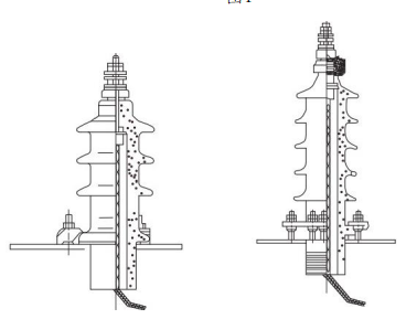
Figure 2 Figure 3
1. Figure 1 is a composite casing, used for voltage of 1 thousand volts and below, current is 300-3000A. Figure 2 is a cable type sleeve, used for a voltage of 10 thousand volts, current is 50-300A. Figure 3 shows a threaded sleeve with a voltage of 35 kV and a current of 35-600A.
2. When the transformer leaves the factory, the casing is assembled on the transformer oil tank and sent to the user together with the transformer.
3. If you need to disassemble or replace the porcelain type, it should be carried out in the following way.
(1) Composite casing, first lift the lifting body, then remove the lead of the lower part of the casing, and finally unscrew all the fastening nuts, remove the casing and replace the replacement casing that has been scrubbed and dried.
(2) For the cable type casing, when replacing the casing, the casing can be replaced externally, and the joint nut should be unscrewed when replaced, and the joint should be pulled with copper wire or yarn belt to prevent slipping into the oil tank, and then removed, porcelain cover, sealing gasket and pressure plate, etc.
4. When installing the casing on the transformer fuel tank, the following matters should be noted:
(1) For composite casing, in order to fully clamp the porcelain part on the box cover of the transformer to prevent oil leakage, the upper and lower parts of the casing must be tightened to fasten the nut of the porcelain part.
(2) For the cable type casing, the nut of the presser screw that fixes the casing must be tightened evenly, and then the conductive rod is fixed after the casing is firmly installed on the transformer oil tank.
5. In perennial use, the casing should be scrubbed frequently according to the dirt situation to prevent the surface of the porcelain sleeve from being discharged.
(2) No excitation tap-changer
The three-phase oil-immersed fully sealed power transformers produced by our company are generally equipped with WSP type no-load tap-changers on the box cover, so as to change the high-voltage side tap-changer when there is no electricity.
1. The typical structure of WSPII1 type non-excitation neutral point voltage regulator tap-changer is shown in Figure 4.
2. For the voltage value indicated by the digital indication of the tap-changer dial in the ±5% voltage regulation range: 1 indicates the tap connector with +5% of the rated voltage value, 2 indicates the rated voltage value, and 3 indicates the tap connector with -5% of the rated voltage value.
3. When changing the position of the tap-changer, the screw on the cover of item 4 must be unscrewed and removed, the handle positioning part of item 3 must be pulled out of the groove hole, and then the item 2 is rotated to the required tap position, and the handle positioning part must be embedded in the corresponding groove hole and covered with a cover.
4. If the tap-changer often works in one position due to the needs of the transformer, in order to eliminate the oxide film and oil stains on the contact part and ensure good contact, regardless of whether the transformer needs to change the voltage, the tap-changer should be rotated at least 10 times a year. If there is no need to change the voltage, it will still be fixed in the original position after rotation, and the tap position should be changed and the bridge or multimeter should be used to measure the path before it can be put into operation.
5. If transformer oil is found to leak out of the tap-changer, find out where it leaks from. If the oil leaks from the transformer fuel tank cover and tap-changer flange, the flat nut of item 6 should be tightened immediately, and if the shaft and flange leak oil, the nut of item 5 should be tightened, but it should not be tightened too tightly to avoid excessive increase in rotational torque.

Figure 4 WSPIII Type 1 tap-changer
If it is the middle voltage regulation, the WPS II.1 non-excitation tap-changer is used, and its operation and maintenance method is basically the same as the above. For non-excitation tap-changers other than the above, please refer to the corresponding tap-changer manual for details.
(3) Pressure release valve
1. Product Usage and Performance Introduction:
Pressure release valves (hereinafter referred to as release valves) are suitable for liquid or gas insulated transformers, transformers, on-load tap-changers, high-voltage switches, capacitors and other products to protect fuel tanks.
When an accident occurs inside the transformer or on-load tap-changer, a part of the transformer is gasified, causing the pressure inside the transformer tank to increase rapidly. If you don't take reliable protection, the tank can deform or even burst. The release valve protects the transformer tank from damage. When the pressure of the fuel tank reaches the working pressure of the release valve, the release valve will be opened within 2 milliseconds to release the overpressure in the fuel tank in time.
Once the release valve is opened, the pressure in the fuel tank drops to about 53-55% of the operating pressure, and the release valve can be reliably closed. This special function of the release valve is the special need of the protection object, which can effectively protect the fuel tank from damage. When the pressure in the tank rises again and reaches the operating pressure, the release valve will act again until the pressure in the tank drops to the normal value. When the transformer is powered on, the 11th safety must be removed.
Because the release valve can be reliably closed after action, the air and water outside the fuel tank cannot enter the fuel tank, and the transformer oil will not be polluted by the atmosphere.
2. Model, specifications, and basic parameters
2.1 model
YSF□-□ □ □
YSF – Pressure Relief Valve Code
□ - Design serial number
□ – Turn on the pressure kPa
□ - the effective caliber of the oil injection mm
□ - Alarm signal environmental conditions and locking device*
※: 1. Used for mechanical signal mark "J".
2. For use in humid tropical areas, add "TH" after the "J" mark.
3. If a locking device is used, then add "B" after it.
For example: YSF6-35/25JTHB
That is, the oil injection diameter φ25mm, the opening pressure is 35kPa, with a mechanical alarm signal, it is used for the damp and hot zone locking device, and the sixth design of the pressure release valve.
2.1 Specifications and basic parameters are shown in Table 1
3. The structure of the structural pressure release valve is shown in Figure 5.
Table 1 Specifications and basic parameters
Effective caliber (mm) | Turn on the pressure (kPa) | Open pressure limit deviation (kPa). | Turn off the pressure (kPa) | Sealing pressure (kPa) |
φ25 φ50 | 15 | ±5 | 8 | 9 |
25 | 13.5 | 15 | ||
35 | 19 | 21 | ||
55 | 29.5 | 33 |
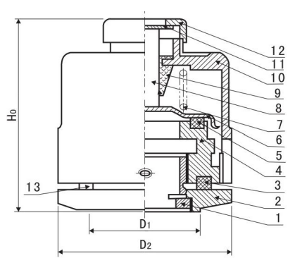
Fig.5 Schematic diagram of the structure of the pressure release valve
4. Use
Choose a release valve equipment with a latching device, and the latching pin should be removed before the equipment is put into operation, otherwise the valve cannot be opened.
After the operation of the pressure release valve during operation, the marker rod should be reset after the fault is found for reuse. The release valve cannot be removed at will during installation.
The pressure release valve has oil leakage, and measures should be taken to solve it in time, and the main reasons for oil leakage are roughly as follows:
a. For some reason, the pressure in the fuel tank is too high, which has exceeded the sealing pressure of the release valve but has not yet reached the opening pressure, causing leakage.
b. Some of the sealing rings in the valve have been aged and failed, and the failed sealant ring should be replaced with the manufacturer in time.
c. If there is a foreign object on the sealing surface, it can be eliminated in time.
5. Maintenance and overhaul
5.1 Take advantage of the opportunity of each power outage maintenance of electrical equipment to carry out the following maintenance of the valve.
a. Whether the opening action is sensitive.
b. Whether the sealing ring has aged, deformed or damaged. If any abnormalities are found, they must be replaced in time to avoid oil leakage or even failure of the release valve due to the aging of the rubber ring.
c. Clear the foreign body in the valve.
d. Whether the parts are rusted, deformed or damaged.
5.2 The user should prepare several release valves in case of replacement during inspection.
(4) Oil sample flap
It is generally installed in the direction of the low pressure side of the lower part of the fuel tank for oil samples. When using, first unscrew the cover, put the oil sample hose on the soft joint 1: then slowly twist the plug until the oil can be released from the connector, and screw the cover on after completion.

Figure 6
(5) Thermometer seat
For measuring the temperature rise of the oil surface of the transformer. The mercury thermometer for measurement is provided by the user. The structure of the thermometer seat is shown in Figure 7. The temperature sensor socket is filled with transformer oil, and when the oil surface temperature rise is measured, just open the cover and insert the mercury thermometer. After measuring, take out the thermometer and tighten the cover again.

Figure 7
(6) Grounding bolts
A grounding bolt is welded to the lower part of the low voltage side of the tank for the overall grounding of the transformer. Its structure is shown in Figure 8. In item 2 washer, the household connection is connected to the grounding busbar, and the bolt of item 3 is tightened to ensure the safe operation of the transformer. For easy identification, there is a grounding sign.

Figure 8
(7) Oil flap
The oil drain valve is installed in the direction of the low voltage side of the fuel tank for transformer accidents or for cleaning and draining oil.
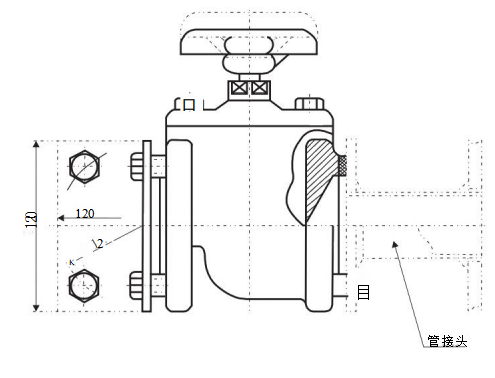
Figure 9

Fully sealed oil-immersed power transformer component
serial number | Code | Name | quantity | Remarks |
11 | tap-changers | 1 | ||
10 | Signal thermometer mount | 1 | There are more than 1000KVA | |
9 | Mercury thermometer holder | 1 | ||
8 | Ground bolt | 1 | ||
7 | Oil sample flap | 1 | ||
6 | Transformer cabinet | 1 | ||
5 | Gas relays | 1 | There are more than 800KVA | |
4 | Low pressure casing | 4 | ||
3 | High pressure casing | 3 | ||
2 | Oil level gauge | 1 | ||
1 | Pressure relief valve | 1 |
----------------------------------------------------------------------------------------------------------------We will present the performance, safe operation methods, and technical parameters of transformer:S9\S11\S13 Liquid Filled Transformers