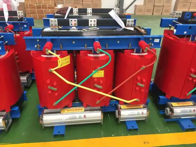
We will present the performance, safe operation methods, and technical parameters of transformer:SC(B) 12\14 dry-type transformer
1. Environmental conditions of product use
1.1 Ambient temperature: upper limit +40°C, lower limit -25°C (indoor);
1.2 The altitude does not exceed 1000m;
1.3 Relative humidity: the daily average is not greater than 95%, and the monthly average is not greater than 90%;
1.4 The intensity of the earthquake does not exceed 8 degrees;
1.5 There is no fire, explosion hazard, serious pollution, chemical corrosion and violent vibration places.
2. Main technical data of transformers:
For details, please refer to the "Product Inspection Report"
3. Inspection before using the transformer
3.1 After long-distance transportation, the transformer should be inspected whether the insulation between the yoke screw, clamp and the core is good, whether the core is multi-point grounded, whether the fasteners are loose, whether the insulation distance between each part of the conductor meets the requirements, and whether the lead wire is damaged.
3.2 The transformer must be checked whether all data meets the requirements before it is put into operation.
4. Transformer operation
4.1 Preparation before transformer operation:
Before the transformer is put into operation, check the nameplate data and whether the nameplate voltage and line voltage match; Check whether the transformer grounding device is good; Whether the transformer insulation is qualified, etc., after checking that everything meets the requirements, the transformer can be put into operation.
4.2 Operating Standards:
(1) Allowable temperature rise: When the transformer is running, under normal conditions, it shall not exceed the temperature allowed by the insulation material. (See the "Product Inspection Report" for the insulation grade)
(2) Allowable load: When the transformer is under load, it heats up due to copper loss and iron loss, the greater the load, the more heat, the higher the temperature rise, when the transformer load is large enough, the transformer may exceed the allowable temperature rise, so it is easy to damage the insulation, for this reason, the transformer operation, there is a permissible continuous and stable load, that is, when the transformer is running, it is generally required not to exceed the rated value specified in the nameplate.
(3) Allowable voltage change: The voltage applied to the transformer during operation can be equal to or less than the rated voltage of the transformer, due to the supersaturation of the transformer core after magnetization, even if a small overvoltage is applied to the transformer, it will cause a large increase in magnetic induction unevenly. The larger the magnetic induction in the transformer, the more the higher the voltage harmonics, the greater the no-load current, the higher the no-load current, the sharper the distortion of the voltage waveform, which is particularly dangerous for higher voltage transformers. According to the above, it is stipulated that the applied voltage of the transformer shall generally not exceed 105% of the rated value of the tap connector, and the current on the secondary side of the transformer shall not be greater than the rated value.
(4) Allowable value of insulation resistance: Generally use a 1000-2500 volt megaohm meter to measure the insulation resistance value. The basic method of measuring the insulation state of the transformer is to compare the insulation resistance value measured during operation with the original data determined before operation. When measuring, under the same conditions of ambient humidity, if insulated
A sharp drop in resistance to 50% or less of the initial value is considered unsuitable.
5. Maintenance, inspection and fault analysis of transformers
5.1 Maintenance of transformers
The load of the transformer should be monitored according to the ammeter, voltmeter, etc. The transformer installed in the substation where there are often personnel on duty should monitor the operation of the transformer according to the instrument on the control panel and read it every hour
When the meter is not in the control room, it should be recorded at least twice per shift. In addition, load adjustment must be carried out. For distribution transformers, their three-phase load should be measured at large loads, and if imbalance is found, it should be redistributed.
In addition to load monitoring, temperature rise must also be monitored. The thermometer installed on the switchboard should also be recorded at least twice per shift.
5.2 Inspection of transformers:
(1) Inspection time: The substation with frequent personnel on duty should inspect the transformer at least once a day.
(2) Inspection content:
External inspection: whether the nature of transformer audio is "buzzing" loud and whether there is a new tone; whether there are abnormal phenomena in cables and busbars; transformer temperature rise, etc.
5.3 Fault analysis of transformers
(1) Insulation reduction: During the operation of transformers, there is often a phenomenon of insulation reduction. The most basic feature of insulation reduction is that the insulation resistance decreases, resulting in an increase in leakage current, serious heat generation, and an increase in temperature during operation, which further promotes insulation aging. or continue, the consequences are very serious, and one of the reasons for the insulation drop is the insulation moisture; The second reason is insulation aging.
(2) Excessive temperature rise: The most obvious symbol of excessive temperature rise is that the ammeter pointer exceeds the predetermined limit, the transformer heats up, and in severe cases, the protective device acts and cuts off the circuit. The reasons for the high temperature rise are:
aExcessive current, excessive load, exceeding the allowable limit of the transformer: Y/Y0-12 connected transformer, overheating will also occur when the three-phase load is unbalanced. The transformer may be disconnected, such as when wiring to the outside one
If the phase is broken, there will be circulation through the inner winding, and a local overload will occur. The clamping bolt of the transformer is loose (this problem is prone to when the transformer is vibrated). The magnetic resistance increases, the reactive load increases, and overcurrent occurs when the same power load is also present. The reverse connection of the winding causes insufficient potential during operation, resulting in overcurrent, and overcurrent will also occur when the transformer is loaded.
b Poor ventilation: dust on the surface of the transformer, blocked air ducts, rising ambient temperature, etc.
c Internal damage to the transformer, such as coil damage, short circuit, etc.
(3) Abnormal sound: When the transformer is running normally, it emits a continuous and symmetrical humming sound, and the sound of each type of transformer is different, and the transformer is loud, and the sound will be loud. Some transformer cores are not staggered, but are first stacked into a whole piece and then pressed with bolts, so the sound is particularly loud during operation, but this sound does not change every time, which has no impact on normal operation. When the sound increases during operation, one is to check whether the applied voltage is too high, and the other is to check whether the core is too loose, if it is too loose, it must be clamped.
When the transformer makes a "squeak" sound, it means that there is flashover, and the sharp part of the metal part of the transformer must be checked to see if it is dull.
When the transformer has a "beep" sound, it means that there is a breakdown phenomenon, which may occur between the coil or the core and the clamp.
(4) Transformer automatic device tripping: At this time, check whether there is a short circuit, overload and secondary line fault outside, if the cause of the fault is not external, the insulation resistance needs to be checked.
(5) Use test methods to check faults: Many faults cannot be correctly judged by external intuitive inspection, such as inter-turn short circuits, internal coil discharge or breakdown, internal coil and external coil insulation breakdown, etc., which must be combined with visual inspection for test measurement in order to quickly and accurately judge the nature and location of faults (see Table 1 for details). The analysis of transformer faults is shown in Table 2.
Table 1: Test items and methods for transformer fault inspection
Pilot project | Test results | Causes of failure | Inspection method |
Insulation resistance measurement (with 1000-2500 volt megaohm meter) coil - coil / coil - ground | Insulation resistance is zero | There is a phenomenon of penetration between coils to the ground or coils | Disassemble to check the coils and insulation |
coil interval And every time I intervene insulating electricity Obstacles are not equal | It could be a damaged bushing | Check the insulation resistance of each phase lead to ground | |
No-load test | The no-load loss and current value are very large | The core screw or yoke screw has a short circuit between the iron core and the iron core, and the grounding plate is installed incorrectly, constituting a short circuit. Short circuit between turns | Check the grounding situation and the short circuit between turns, use a 1000 volt megaohm meter, measure the insulation resistance of the iron screw, check the insulation condition of the clamp, when the first phase is short-circuited, measure PAC/PAB=PAC4PBC≤25%, If this does not match, it indicates a short circuit between turns |
The no-load loss is very large | Poor insulation between iron chips | DC voltage, current method, and insulation resistance of the paint film between the pieces are measured | |
No-load current is large | The iron core seam is poorly assembled silicon steel sheet and the amount is insufficient | Observe the core seam and measure the core cross-section | |
Short circuit test | The impedance voltage is very large | The parts are poorly connected | Segmented DC resistance measurement |
The short-circuit loss is too large | there is a break in the parallel wire, and the transposition is incorrect; Fewer wire cross-sections | Short circuit the low voltage, when the high voltage Y is wired, respectively in AB, BC, CA wire end pressure, three short circuit tests, each The results of the measurement are analyzed and compared, and when the high-voltage △ is wired, it should be shorted to one phase | |
Coil connection group measurement | Results The same company The connections are inconsistent | One of the coils in a phase coil is in the opposite direction | The connection group measurement method is used to find out the wrong part of the coil |
Table 2: Transformer fault analysis
fault | phenomenon | Causes of failure | Inspection method |
1. Iron core part | |||
The insulation between iron chips is damaged | The loss of empty load increased | The insulation between iron chips is aging and there is internal damage | For visual inspection, the insulation resistance between pieces can be measured by DC voltage and current method |
Local short circuit of the iron core and partial melting of the iron core | Signal loop action | Insulation damage of core yoke screws; There are metal parts at the fault that short-circuit the iron chips and the inter-piece damage Serious bad; Incorrect grounding method constitutes a short circuit | For visual inspection, the insulation resistance between pieces can be measured by DC voltage and current method |
The ground plate breaks | When the voltage rises, a slight discharge sound may occur inside | Check the grounding tab | |
Abnormal loud noise | 1. Missing pieces or multiple pieces in the iron core lamination 2. There is an unclamped free end in the core airway or under the clamp 3. The core fastener is loose | 1. The patch or pull out the piece should ensure that the core is clamped 2. Plug and press the free end tightly with insulation 3. Check the fasteners and tighten them | |
2. Coil | |||
Short circuit between turns | 1. The primary current is slightly higher 2. The DC resistance of each phase is unbalanced 3. When the fault is serious, the differential protection action, such as the overcurrent protection device installed in the power supply test, does not work | 1. Due to natural damage, poor heat dissipation, or long-term overload, the inter-turn insulation is aging. 2. Due to the short circuit or other faults of the transformer, the coil vibrates and deforms, and damages the insulation between turns 3. Defects not found during coil winding | 1. Visual inspection 2. Measure DC resistance |
The coil is broken | An arc occurs at the broken wire | Leads are broken due to poor connection or short-circuit stress; The internal welding of the wire is poor, and the short circuit between turns causes the wire turn to burn. | If the coil is a triangular connection, you can use an ammeter to check the phase current of the coil or measure the DC resistance, and if the coil is a star connection, you can use a 1000 volt megaohm meter to check it |
Ground breakdown | 1. The main insulation is cracked, broken or defective due to aging. 2. There are debris falling inside the coil. 3. Overvoltage action. 4. The coil is deformed and damaged when the short circuit is conducted. | 1. Use a megaohm meter to measure the insulation resistance of the coil to the ground 2. Visual inspection | |