We will present the performance, safe operation methods, and technical parameters of HXGN-12 medium-voltage switchgear
1. Scope of use

HXGN□-12 (F.R) box-type fixed AC metal enclosed switchgear (referred to as "ring network cabinet") is a new type of switchgear designed for the renovation and construction of urban power grids. It is also used as a breaking load current, short circuit current and closing dish current in the power supply system, and is suitable for AC 3-10KV, 50Hz power distribution system. It is widely used in urban power grid construction and renovation projects, industrial and mining enterprises, high-rise buildings and public facilities, etc., as a ring network power supply unit and terminal equipment, playing the role of power distribution, control and protection of electrical equipment, and can also be installed in pre-installed substations. This ring network cabinet is equipped with a vacuum load switch and a spring operation mechanism, which can be operated manually or electrically. The grounding switch and isolation switch are equipped with manual operation mechanisms, and the complete set of this ring network cabinet is strong and small. There is no risk of combustion and explosion, and it has a reliable "five prevention" function. This ring network cabinet complies with the relevant provisions of GB3960 "3~35KV AC Metal Switchgear" and IEC60420 "High Voltage AC Load Switch-Fuse Combination Electrical Appliances" standard.
2. Model and its meaning
HXGN□-12(F.R)
H: Ring network
X: Box type
G: Stationary
N: Indoor
□: Design serial number
12: Rated voltage
(F.R): Load switch-fuse combination
3. Normal conditions of use
1. Ambient air temperature: -15. 0+40℃;
2. Altitude: 1000m and below;
3. Humidity conditions: the daily average is not more than 95%, the daily average water vapor pressure is not more than 2.2kPa, the monthly average is not more than 90%, and the monthly average water vapor pressure is not more than L 8kPa;
4. Earthquake intensity: no more than 8 degrees;
5. There are no obvious pollutants such as corrosive or flammable gases.
Note: If the above normal conditions of use are exceeded, the user may negotiate with the Company.
4. Main technical parameters
serial number | name | unit | data | |
1 | Rated voltage | KV | 12 | |
2 | Rated current | Load switchgear | A | 630 |
Combined switchgear | 125 | |||
3 | Rated short-circuit breaking current | KA | 31.5 | |
4 | Rated active load breaking current | A | 630 | |
5 | Rated for short-term withstand current | KA | 20 | |
6 | Rated peak withstand current | KA | 50 | |
7 | The rated power frequency is rated to withstand voltage interphase, ground/break | KV | 42/48 | |
8 | Lightning shock is resistant to voltage phase, ground/break | KV | 75/85 | |
9 | Mechanical life | times | 10000 | |
10 | Rated Handover Current (Combined Appliances) | A | 3150 | |
11 | How it works | Manual or electric | ||
12 | Protection level | IP3X | ||
5. Structural characteristics (as shown in Figure 2 and Figure 3)
1. Structural performance characteristics
1.1.1 The ring network cabinet adopts 8MF profile, and the whole frame is installed with modulus holes B=2 (tan.
L1.2 ring network cabinet is equipped with FZN21-12D load switch or FZRN21-12D fuse combination electrical appliance, which has an isolation switch, a vacuum load switch, and a grounding switch, and the disconnect switch and grounding switch have obvious breaks.
1,3 The isolation switch, vacuum load switch, grounding switch, and cabinet door have perfect and reliable digging and interlocking devices, which can effectively prevent misoperation and ensure safe maintenance.
1.1.4 It can be operated manually and electrically.
1. The cabinet door and instrument door of the L5 measuring cabinet are equipped with sealing pins.
1.1.6 Fuse combination electrical cabinet and melt tube with firing pin. In the case of a short circuit, the firing pin hits the tripping mechanism to achieve rapid opening and breaking, which can effectively protect the electrical equipment.
1.L 7 ring mesh cabinet adopts front operation, reliable wall installation.
2. "Five prevention" locking function
2. 2.1 Power transmission operation: Only when the cabinet door is closed and locked, and the ground switch is operated to the "open" position, the load switch can be operated to close the position.
2.2.2 Power outage operation: When the load switch is in the isolation position, the grounding switch can be closed, and when the grounding switch is in the closed position, the insulation partition is inserted into place to open the cabinet door.
2.1. 3 The vacuum interrupter is reliably interlocked with the isolation knife, and the isolation knife and the grounding knife are linked to each other and interlocked with the cabinet door, and the insulating partition is also interlocked with the cabinet door.
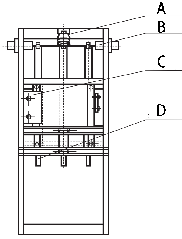 | Figure 2 A: Insulator B: Through the wall casing C: Operating mechanism D: Grounding switch |
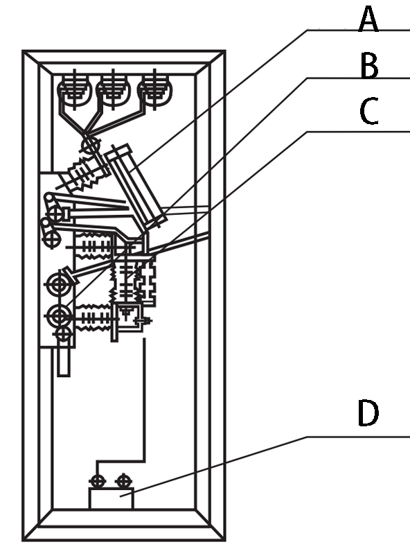 | Figure 3 A: Fuse (isolation knife gate) B: Bullet control mechanism C: Load switch D: Current transformer |
6. The principle of ring network power supply
The ring network power supply < consists of three basic units (see figure) The inlet and outlet line cabinets are used as ring network units, which can be isolated in time when any fault occurs, and another unit ensures the continuous power supply of the user's transformer branch. The user loop network cabinet plays a role in protecting and isolating the transformer, which is convenient for maintenance and overhaul. The ring network cabinet can be arbitrarily extended, and can be composed of a variety of combination schemes from basic units according to user requirements.
 | ||
| Cable inlet and outlet line cabinet User transformer branch cabinet Cable entry and exit line cabinet |
7. Main circuit scheme diagram
Scheme number | 01 | 02 | 03 | 04 | 05 | 06 |
Main circuit scheme diagram |  | |||||
use | Cable in and out of the line | Cable in and out of the line | Cable in and out of the line | Cable in and out of the line | Cable in and out of the line | Cable in and out of the line |
Isolation/load/combination appliances | GN□-12D | GN□-12D | GN□-12D | FZN21-12D | FZN21-12D | FZN21-12D |
Fuse | RN3 | RN3 | ||||
Current transformer | LZZBJ9 | LZZBJ9 | ||||
arrester | HY5W | |||||
Scheme number | 07 | 08 | 09 | 10 | 11 | 12 |
Main circuit scheme diagram | 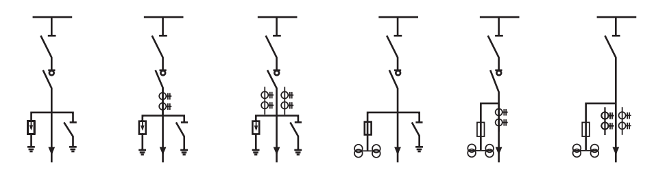 | |||||
use | Cable in and out of the line | Cable in and out of the line | Cable in and out of the line | Cable in and out of the line | Cable in and out of the line | Cable in and out of the line |
Isolation/load/combination appliances | FZN21-12D | FZN21-12D | FZN21-12D | FZN21-12D | FZN21-12D | GN□-12D |
Fuse | RN2 | RN2 | RN2 | |||
Current transformer | LZZBJ9 | LZZBJ9 | LZZBJ9 | LZZBJ9 | ||
Voltage transformer | JDZ | JDZ | JDZ | |||
arrester | HY5W | HY5W | HY5W | |||
Scheme number | 13 | 14 | 15 | 16 | 17 | 18 |
Main circuit scheme diagram |  | |||||
use | metering cable inbound and outbound lines | Cable in and out of the line | Cable in and out of the line | Cable in and out of the line | metering cable inbound and outbound lines | Overhead incoming cable outlet |
Isolation/load/combination appliances | FZRN21-12 | FZRN21-12D | FZRN21-12D | FZRN21-12D | GN□-12D | |
Fuse | RN2 | S□LAJ | S□LAJ | S□LAJ | RN2 | RN3 |
Current transformer | LZZBJ9 | LZZBJ9 | LZZBJ9 | LZZBJ9 | ||
Voltage transformer | JDZ | JDZ | ||||
Scheme number | 19 | 20 | 21 | 22 | 23 | 24 |
Main circuit scheme diagram |  | |||||
use | Overhead incoming cable outlet | Overhead incoming cable outlet | Overhead incoming cable outlet | Overhead incoming cable outlet | Overhead incoming cable outlet | Overhead incoming cable outlet |
Isolation/load/combination appliances | FZRN21-12D | FZRN21-12D | FZRN21-12D | FZRN21-12D | FZRN21-12D | FZRN21-12D |
Fuse | S□LAJ | S□LAJ | S□LAJ | S□LAJ | ||
Current transformer | LZZBJ9 | LZZBJ9 | LZZBJ9 | LZZBJ9 | ||
Voltage transformer | ||||||
Scheme number | 25 | 26 | 27 | 28 | 29 | 30 |
Main circuit scheme diagram |  | |||||
use | contact | contact | Measurement and liaison | Measurement and liaison | Overhead line contact | Overhead line contact |
Isolation/load/combination appliances | FZRN21-12 | FZRN21-12D | FZRN21-12D | FZRN21-12 | ||
Fuse | S□LAJ | RN2 | RN2 | S□LAJ | ||
Current transformer | LZZBJ9 | LZZBJ9 | ||||
Voltage transformer | JDZ | JDZ | ||||
8. Shape and installation size
1. The overall size of the ring network cabinet
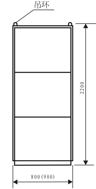 |  | Cabinet width direction |
| Description: The height can be selected | cabinet depth direction |
2. Installation size of ring network cabinet
 |
| Note: The channel steel should be reliably grounded |